Interact Analysis has published an analysis of the market for battery packs for off-highway EVs, and found that Hamburg-based material handling company Jungheinrich has by far the largest market share in the category.
Jungheinrich led the market-share rankings for battery packs for loaders, telehandlers, excavators and tractors in Europe/Middle East and the Americas.
According to the report, most of Jungheinrich’s sales are confined to several customers in the construction industry that also happen to ship higher-than-average numbers of battery-electric vehicles. The company does not offer products suitable for larger, high-voltage off-highway equipment.
The report identified some 20 companies active in the sector, a figure that shows growth in the off-highway sector, given that the number was in the low single digits not too long ago. At the top, following Jungheinrich, were BorgWarner, Forsee Power, Turntide, Volvo and Wamtechnik.
Compared to off-highway vehicle sales overall, it is still early days for the sales of electric vehicles. According to Interact Analysis, the current cost of battery packs is a key reason why this is the case, and sales will likely only increase in a meaningful way when the price of an off-highway EV is down to 1.5 times the price of its fossil fuel-powered equivalent, versus the current two times.
Japanese electronics company TDK Electronics has launched its L862 (B57862L) NTC thermistors with bendable wires and the L871 (B57871L) lead spacing NTC thermistors that can be used in automotive and industrial applications.
The thermistors can be used in automotive battery packs as well as power banks, energy storage and drones. They offer short response time and high measuring accuracy.
Both series are lead-free and can measure temperatures between -40° C and +155° C with a tolerance of ±1% and ±3% respectively. At room temperature, their maximum power dissipation is 60 mW. Both series are available with different rated resistances between 1 kΩ and 100 kΩ and different R/T characteristics. After 10,000 h at +70° C, the deviation of the resistance at room temperature R25 is less than 3%.
The sensor element of the L862, which is encapsulated with a black epoxy coating, is just 2.6 x 6.5 mm (D x H) in size and has insulated leads of silver-plated nickel wire (AWG 30, Ø 0.25 mm). The total length of the sensor including the wires is 50 mm, with 6 mm stripped. While the dissipation factor (δth) of the sensor is 1.4 mW/K, its thermal cooling time constant (τc) is 14 s.
The sensor element of the L871 is also encapsulated with a black epoxy coating. It is just 2.8 x 6.0 mm (D x H) in size and has copper-clad steel wires (Ø 0.4 mm) with a spacing of 2.5 mm. The dissipation factor of the sensor is 3 mW/K, and its thermal cooling time constant is 9 s.
LION Smart, a subsidiary of battery pack manufacturer LION E-Mobility, has entered into a strategic partnership with hofer powertrain. The two companies intend to develop and commercialize immersion-cooled battery systems with high market potential.
The two companies mean to combine their strengths to bring new battery systems to market maturity. hofer powertrain contributes expertise in the development, validation and rapid implementation of battery systems tailored to specific customer requirements. LION Smart complements this with its immersion-cooled battery technology, which boasts high thermal stability, improved safety and increased power density compared to current battery designs.
LION E-Mobility has a current annual production capacity of 2 GWh, and operates highly automated module assembly lines at its own production facility in Germany.
“With hofer powertrain, we have a strong partner by our side that perfectly complements our innovative strength. Together, we are accelerating the market entry of our highly innovative high-performance batteries and delivering pioneering solutions for sustainable mobility,” says Joachim Damasky, CEO of LION E-Mobility.
“hofer powertrain stands for innovation, speed, and precision in the development and industrialization of sophisticated drivetrain systems,” adds Johann Paul Hofer, CEO of hofer powertrain. “The partnership with LION Smart builds precisely on this and opens up new possibilities to transfer cutting-edge battery solutions into industrial applications.”
Trova Commercial Vehicles has launched a battery-electric terminal truck, the company’s first product to reach the market.
Terminal trucks are semi-tractor vehicles designed to move semi-trailers within a warehouse facility, cargo yard or intermodal facility.
“One of the unique sides of Trova is its leadership team,” Collignon told Charged, explaining that the team includes several former senior executives of Volvo, owner of Mack Trucks—among them the former President of Mack Trucks and an Executive Vice President of Volvo.
Another unique attribute Collignon mentioned was Trova‘s enterprise model, which is based on a constellation of subject-matter-expert companies. “We refer to it as a multi-stakeholder model, similar to the Japanese keiretsu,” Collignon said. Keiretsu refers to the Japanese model of an interdependent group of companies, each with its own banking partner, manufacturers, distributors and supply chain partners. He added that this network was incubated in 2014 and has been responsible for several achievements, the launch of Trova being one of them.
“We were accompanied on our journey by two strategic partner companies: Netgroup, an automotive engineering firm, and Chateau Energy Solutions, with whom we offer complete infrastructure solutions including EV charging stations, to our customers,” Collignon told us.
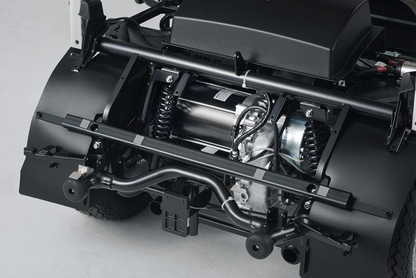
“The terminal tractor’s chassis has been designed from the ground up for our high-voltage driveline,” he added, noting that the battery packs were located inside the chassis rails. Trova believes this approach assists with overall safety and vehicle stability. The company does not use rail-mounted battery packs, to avoid exposure to side-impact accidents and reduce the amount of structural steel needed to mount the battery packs, which in turn reduces the overall weight of the vehicle.
Collignon also said that “the HV architecture consists of 5 pre-assembled modules, which not only reduces assembly time but also improves accessibility for aftermarket maintenance and repair.”
The vehicle is equipped with a full-width cab with room for a second seat, an unusual feature for such trucks, but one Collignon said had been designed based on feedback from potential customers. This included discussions with tractor terminal drivers who complained about a cramped workspace or insufficient space for driver training. Trova’s is the most spacious cab in the industry, Collignon said.
Trova worked with the Industrial Design department at Virginia Tech in designing the cab, which includes a space frame, a platform cab with structural integrity built into the space frame, and side impact bars that double as ergonomic arm rests. The interior height is above the industry norm, allowing a person who is 6 feet tall to stand up at the entrance, while the front windshield and side windows lean forward to offer improved low-speed visibility in inclement weather, Collignon said.
“The climate control of the cab is integrated into the proprietary thermal management system and offers air conditioning as a standard feature,” he added.
Collignon told us the truck is the first vehicle in its market segment to use axial flux motors. “These motors are very compact, with high performance and fewer magnets, which translates to less impact on the environment thanks to less reliance on rare earth metals.” The system‘s nominal voltage is 660 V.
As for the company’s name, Trova, this reporter asked whether this might have been taken from the Latin verb for “to find.” Collignon enthusiastically confirmed this, saying, “We seek to find solutions to accelerate the market acceptance of battery-electric commercial vehicles.”
UK-based technology startup Flint Engineering has unveiled IsoMat, which aims to reinvent traditional heat pipe technology through a flat aluminum sheet design, featuring an internal network of sealed channels.
When exposed to temperature differentials, the liquid within the channels undergoes a rapid cycle of evaporation and condensation, resulting in near-instantaneous heat transfer across the entire surface. This enables thermal energy transfer approximately 5,000 times more efficiently than copper or aluminum alone, according to the company.
When incorporated into battery pack casings, IsoMat distributes thermal energy evenly, maintaining batteries at an optimal 25° C (±1° C).
“We’re seeing unprecedented interest across the construction, electrification, and refrigeration sectors—yet these industries represent just a snapshot of the potential for this game-changing innovation. Commercial deployment is scheduled for this year, and we’re preparing to engage with venture capital communities. We’re actively seeking partnerships and welcome ideas from companies across all sectors,” said Mark Robinson, CEO of Flint Engineering.
Proventia, a supplier of emission control systems, thermal insulation components and batteries, has introduced its new Proventia Energy LFP-based battery pack.
Lithium iron phosphate (LFP) technology is a good option for heavy machinery due to its cost efficiency and long lifespan, the company said. The high-energy, high-voltage battery systems are suitable for continuous operation over extended periods.
“The benefits of this new product are remarkable, from exceptional engineering to high-quality European origins,” the company said, referring to its use of cells from Morrow Batteries, a Norwegian cell producer.
Proventia explained that the LFP chemistry inside the battery pack “delivers consistent energy,” making it well-suited to applications such as heavy work machines, wheel loaders and tractors, among others. It can be incorporated within either an electric installation or a hybrid installation.
In addition, the Proventia Energy battery pack supports more cycles, over 6,500 charges, and operates throughout a wider temperature range, -20° C to +55° C, than the company’s lithium titanate oxide (LTO) batteries. The LFP battery packs can utilize the full capacity of the battery, Proventia said.
The LFP technology in Proventia Energy battery packs is also more environmentally friendly than LTO technology, the Finnish company said, because it does not contain nickel, cobalt or manganese.
Proventia will showcase the new battery at the Bauma—shorthand in German for Baumaschinen, or construction equipment—a triannual trade show held in Munich for construction machinery, building material machines, mining machines, construction vehicles and construction equipment.
Yamaha Motor has announced the debut of two new five-seat golf cart models that utilize new lithium iron phosphate (LFP) batteries that it has developed and begun manufacturing.
Two variants are available, the electromagnetically-guided G30Es and the manually-operated G31Eps.
Both models are 144.5” in length, 49.5” in width, 73” in height and have an 84.25” wheelbase, and are available with a battery capacity of either 4 kWh or 6 kWh.
The use of LFP in the batteries’ design affords both high reliability and an extended lifespan, Yamaha said, adding that LFP batteries are known for high thermal stability.
Golf carts are in use on many corporate and manufacturing campuses to get staff and visitors from point A to point B. They are also used in airports, on college and university campuses, at hospitals and for event transportation.
A high-precision AC motor offering “superior speed and torque control, combined with optimized regenerative braking and a brushless design,” gives the carts far greater efficiency than the company’s previous models, resulting in 30% lower power consumption, Yamaha said.
Both variants will be launched in Japan in June 2025, and in Taiwan at a later date.
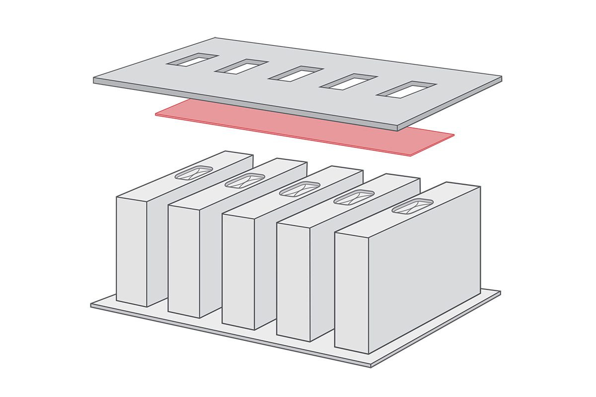
Avery Dennison Performance Tapes has introduced a new EV Battery Venting Materials Portfolio to help counter the risk of thermal runaway and increase safety in EV batteries. These venting solutions include single- and double-coated anisotropic filmic tapes with proprietary fire-barrier coatings and pressure-sensitive adhesives (PSA) for bonding.
EV battery manufacturers implement venting strategies at the cell, module and pack levels. The Avery Dennison battery venting tape solutions, when applied to module- or pack-level venting holes, provide quick burn-through to facilitate venting via a channel. The opposite side provides extended flame resistance to prevent the migration of flames and hot gases into adjacent cells. The outer side of the film will last less than 4 seconds under flame. The adhesive side will last longer than 15 seconds. The combined flame retardancy is designed to counter the risk of thermal runaway.
“Our new venting solutions are engineered to provide differential performance to flame exposure, which can lead to very elegant emergency venting strategies,” said Max Van Raaphorst, Business Development Manager, eMobility, Automotive & Energy Storage, Avery Dennison Performance Tapes North America. “These unique tapes can be combined with a wide range of other thermal runaway mitigation materials to lead to efficient, space saving designs. As always, our goal is to help make EV battery packs more safe, efficient and easier to assemble.”
The vast majority of EV traction motors must be supplied with sinusoidal 3-phase alternating current with the frequency proportional to RPM, and the overwhelmingly favorite way to do this is with a triple half-bridge voltage source inverter, or VSI.
In this topology, each bridge switch can connect its output terminal (i.e. motor phase winding) either to the positive or the negative rail of a voltage source (i.e. the battery in an EV, hereafter referred to as +Vbatt and -Vbatt), ignoring the useless choice of both switches being off, and the destructive choice of both being on, hence this type of inverter is further described as “2-level.”
The output waveform of a 2-level inverter operating at the fundamental frequency is a square wave, and while it is possible to drive AC motors with square waves, they don’t much like it because of the high harmonic content, which produces excessive heating, a reduction in maximum achievable torque at any RPM, and more vibration. The traditional approach to reducing the harmonic content is by chopping each output pulse up into many slices and modulating their on times, or duty cycles, sinusoidally. The inductance of the motor windings then integrates this pulsating voltage waveform into a sinusoidal current, with a consequent improvement in torque, vibration and losses. The higher the PWM frequency—i.e. the more slices for each output pulse—the lower the total harmonic distortion, or THD, in the current waveform, which can only be a good thing…up until it isn’t, anyway.
The first major obstacle to increasing the PWM frequency without end is that the percentage of time spent in the switching transitions (i.e. off to on and on to off) increases unless the switches are also proportionally faster. As the switch effectively acts like a resistor during the transitions, these so-called switching losses increase with PWM frequency, all else being equal. However, employing faster switches—such as the latest technology SiC MOSFETs and GaN HEMTs (High Electron Mobility Transistors)—leads to its own set of headaches, as just because you can switch 400 to 800 V in 10-30 ns with these technologies doesn’t mean you should; the extremely high dV / dt of such rapid switching produces prodigious amounts of RF noise, and also causes winding insulation and shaft bearing-destroying common-mode currents to flow. In fact, a rule of thumb says that the effective RF bandwidth, in MHz, of a switching transition, in ns, is 350 / dV / dt; e.g. a 10 ns switching time will generate significant RF energy out to 35 MHz.
One solution to soften the switching transitions without slowing down the switches is to add an LC low-pass filter directly after each inverter output (especially if the motor is more than a few meters away, as the interconnect cables make embarrassingly good radio antennas). Setting the filter’s cutoff frequency to 1/10th the effective bandwidth frequency as calculated above (e.g. 3.5 MHz for the previous example) will suffice for softening the transitions, which will drastically reduce offending RF noise emissions while not introducing enough phase shift to cause problems with vector motor control schemes. These so-called dV / dt filters won’t help much with reducing the common-mode currents, though, as the motor voltage waveform will still very much consist of pulses that span the full battery voltage.
To effectively integrate the chopped voltage waveform into a nice sine wave (i.e. same as the current waveform) would require the LC filter cutoff frequency be no higher than 1/10th the actual PWM frequency, and that would take up a lot more volume (and cost more) while almost certainly introducing enough phase shift to interfere with vector control schemes if not addressed in hardware and/or software.
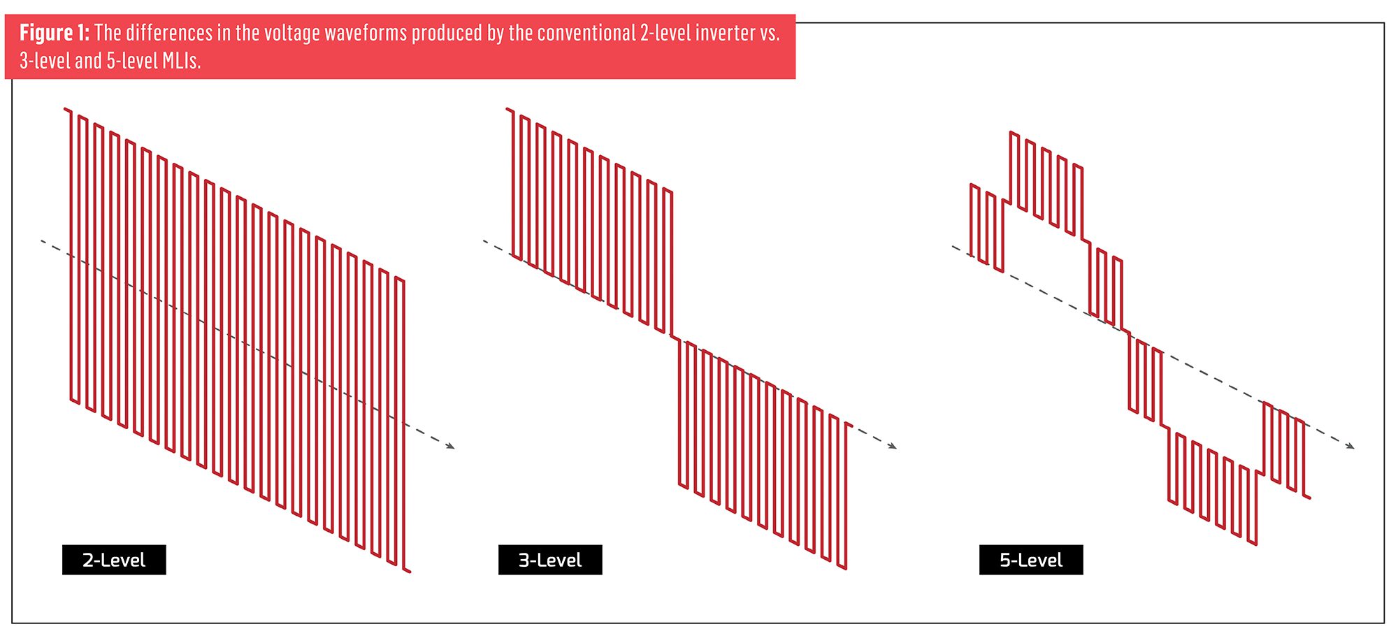
Another way to lower the THD and reduce the magnitude of common-mode currents is to add more steps to the voltage waveform generated by the inverter—a multilevel inverter, or MLI, in other words. Figure 1 illustrates the differences in the voltage waveforms produced by the conventional 2-level inverter vs 3-level and 5-level MLIs. It’s difficult to see how the 2-level inverter even produces a sinusoidal current, whereas it’s much more obvious in the 3-level and 5-level MLIs. Note also that each PWM pulse in the 2-level inverter swings the full battery voltage, but only half Vbatt for the 3-level MLI, and a quarter of Vbatt for the 5-level MLI, etc. The price you pay for lower THD and common mode currents at a given PWM frequency with all multilevel inverter topologies is that they are much more complicated than their 2-level progenitor (ridiculously so, in some cases), and might very well not be worth paying for when compared to the more band-aid-type solutions of additional LC filtering, hardening of the motor against common-mode currents, etc.
Multilevel inverters obviously need access to separate voltage sources for each output voltage level, or else must create the voltage levels indirectly.
Multilevel inverters obviously need access to separate voltage sources for each output voltage level (and each motor phase, for some MLI topologies), or else must create the voltage levels indirectly (typically with capacitive voltage dividers). An example of the former type of MLI is the Cascaded H-Bridge, which has found some use in industrial applications because the separate DC voltages can be supplied by a mains transformer with multiple secondaries, but won’t be considered further here because it would require a Rube Goldberg-like arrangement of isolated battery packs and chargers in an EV.
A far simpler way to generate the different voltage levels is the capacitive voltage divider (examples of such for 3- and 5-level MLIs shown in Figure 2), which acts just like a resistive voltage divider, though only for alternating currents. Wiring two equal-value capacitors in series will divide the bus voltage in half, and the midpoint will become a new 0 V reference for the MLI (i.e. the power stage of a 3-level MLI generates pulses with amplitudes of +Vbatt / 2, 0 V, or -Vbatt / 2, with respect to the midpoint).
The divider function can be extended by adding more pairs of capacitors, in which case the midpoint of each junction becomes a new voltage level (so the 4-capacitor divider string for a 5-level MLI creates voltage levels of +Vbatt / 2, +Vbatt / 4, 0 V, -Vbatt / 4 and -Vbatt / 2, once again assuming all capacitor values are equal).
Neutral Point Clamped and Flying Capacitor types of multilevel inverter topologies use the same basic power stage structure but different methods of generating the 0 V output level.
As advantageous as reducing the voltage swing of the pulses might be, the law of diminishing returns will kick in at some point, as the sheer volume of the capacitors required—and the complexity of the rest of the MLI—scales directly with the number of voltage levels. It is also important to note that the capacitors in the voltage dividers have to carry considerable ripple current, both at the fundamental (motor) frequency and the PWM frequency, meaning that they will likely need to have relatively large capacitance values (to minimize ripple voltage from the low-frequency currents) and a film dielectric (to minimize losses from the high-frequency currents), which is not terribly cost- or volume-effective.
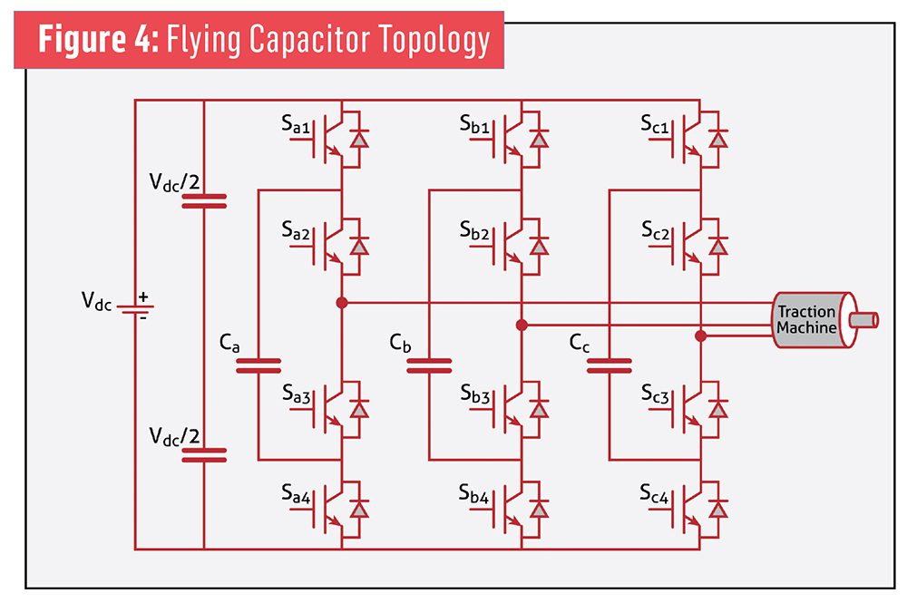
Two of the original multilevel inverter topologies that could be used in EVs are the Neutral Point Clamped (NPC) and Flying Capacitor (FC) types, shown in Figures 3 and 4, respectively, which use the same basic power stage structure but different methods of generating the 0 V output level. In each of these 3-level MLIs, a phase winding is connected to +Vbatt when the upper two switches are on, or -Vbatt when the lower two switches are on, but the 0 V output level is generated directly in the NPC type by turning on the inner two switches, while in the FC type it is generated indirectly by turning on the upper and lower-inner switches at the same time to charge the flying capacitor, followed by the upper-inner and lower switches to discharge it. Neither of these methods allow for actively balancing charge on the divider capacitors, so there tends to be more voltage ripple across them, and as mentioned above, the more ripple on the divider capacitors, the higher the THD. The NPC type is easier to control (far easier, in fact), while the FC type has higher fault tolerance (a capacitor is in series with the motor windings during the 0 V state) and can achieve a lower ultimate THD, but it is fiendishly difficult to control and introduces the thorny problem of how to pre-charge its flying capacitors during startup.
Two MLI topologies that use active switches to better maintain charge balance on their divider capacitors while preserving the ability to handle loads with a wide power factor range (read: induction motors) are the Active Neutral Point Clamped (ANPC) and the T-type, shown in Figures 5 and 6, respectively.
The ANPC MLI replaces the clamping diodes in the NPC with switches that are turned on in conjunction with their respective middle bridge switch to clamp that winding to a capacitor midpoint. The key difference in operation compared to the passive clamping with diodes is that the on time of the clamping switches can be varied to better control the charge balance on the divider capacitors.
The T-type MLI operates in a similar fashion but saves two switches by replacing the clamping and inner bridge switches with a single bidirectional switch (composed of two conventional unidirectionally-blocking switches wired back-to-back) that directly connects a phase winding to a divider midpoint while allowing for bidirectional current flow when on, and bidirectional blocking when off. The main advantage of the T-type inverter is that it uses a standard triple half-bridge for driving the motor, but that also means the bridge switches must be rated to comfortably withstand the full battery voltage, whereas all of the other MLI topologies considered here stack two switches in series at the outer (highest voltage) bridge positions (the inner switches only see a fraction of Vbatt), so all of the switches can theoretically be rated for half the blocking voltage (in a 3-level MLI). That’s particularly helpful for current-technology GaN HEMTs as they most commonly top out at a 650 VDC rating, but not so relevant with SiC MOSFETs (or older-technology Si IGBTs) as they are widely available in the 1.2 kV and 1.7 kV ratings that would be appropriate for battery voltages in the 600-800 VDC range.
There are numerous other MLI topologies that are even more complex, but they won’t be considered here—the considerable increase in component count going from a 2-level VSI to any of the 3-level (much less 5-level!) MLI topologies is enough of an obstacle to their adoption as it is. Another obstacle is that all of the MLI topologies require changes to the power stage switch control schemes, which means their development will be far more costly (and take more time than anticipated—but isn’t that always the case?). When one also considers that just the AC voltage divider capacitors required by most MLI topologies will likely take up as much volume all by themselves as a complete 2-level VSI (to say nothing of the flying capacitors also required in the FC MLI), and that a substantial reduction in RF noise emissions—and even common-mode noise currents—can be achieved in the 2-level VSI simply by adding LC filters to each phase output, the argument for MLIs in EVs is a tough one to sell.
This article first appeared in Issue 70: October-December 2024 – Subscribe now.
Dutch battery manufacturer LeydenJar has developed and produced lithium-ion batteries with a 100% silicon anode capable of delivering 500 charge-discharge cycles without requiring any external pressure, overcoming a key limitation of next-generation anodes.
Silicon anodes offer the potential of higher energy density for lithium-ion batteries when replacing traditional graphite anodes. However, a major challenge has been the tendency for silicon to swell during charge-discharge cycles. This swelling can damage the cell internally, causing early degradation and failure.
Researchers typically use heavy clamps to apply high amounts of external pressure to cells that have silicon-dominant anodes during operation to maintain the anode’s structural integrity. This limits the practicality of silicon anodes.
LeydenJar’s silicon anode features a porous architecture that effectively accommodates the expansion and contraction of the silicon during cycling, ensuring the structural integrity and long-term performance of the cell.
The company is exploring new applications in sectors such as electric vehicles, energy storage and wearables.